Introduction

Principle & Structure

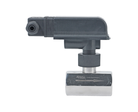
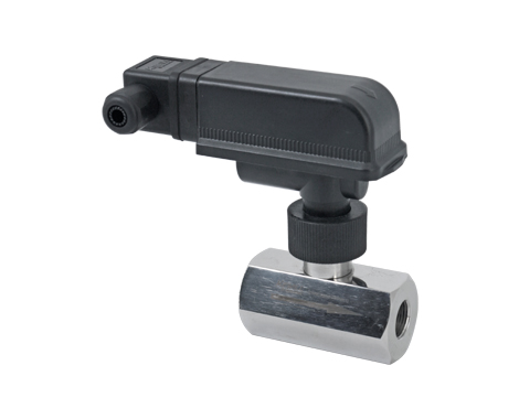
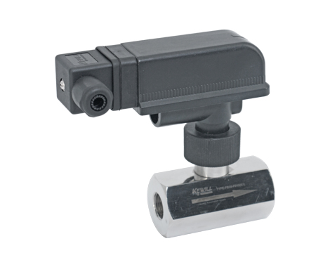
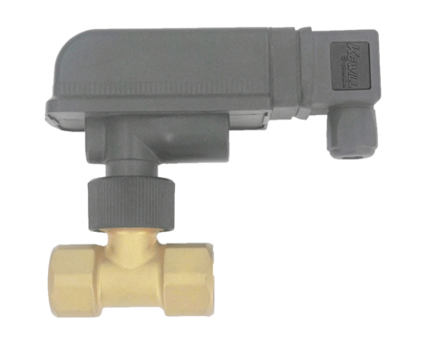
The flow switch consists of a vane system (1) at its other end connected to a permanent magnet (2), on top of this magnet is a reed contact (3), this part is placed on the outside of the liquid. There is also a magnet (4) which has the same pole as the previous magnet and generates a certain force to reset the switch to the no-flow position.

When the liquid rushes to the baffle, the baffle swings, changing the relative position of the magnet (2) and the reed contactor (3), activating the contactor, and once the liquid flow is interrupted, the blade returns to the starting position, activating again contactor. The mutual repulsion of the two magnets eliminates the force required to reset the magnets. Use magnetic force instead of normal spring components to achieve stable and durable use and no sensitivity to pressure peaks.

Features

● Low pressure drop switch point measurable

● Instant response pressure 250bar

● On and off depends only on flow, not on temperature or pressure

● The reed contactor as the induction element is composed of two magnetic pieces, which are placed in a glass tube filled with inert gas. This method eliminates the loss caused by the burning of the contact.

● The switch point can be measured

● Pressure 250bar

optional features

special set point

LED inside the plug to show flow

Pressure resistance 250bar optional

Reed contactors with high switching performance

technical parameter

Bellows life:100,000,000 times
Repeatability:±2.5% of total scale
Hysteresis:Depends on switching point, min. 0.5L/Min
Wiring:Terminal wiring
Pressure resistance:16bar (250bar optional)
Medium temperature:0…90℃(-30…50℃)
Ambient temperature:-25…80℃
Maximum switching current:1A
Maximum switching voltage:230VAC,48VD
Maximum capacity:26VA,20W
Protection class:IP57
Material:
main body:Electrical main body:Plastic NORYL PPO GFN3
Process connection:Bronze Gold / Stainless Steel 1.4301 (304)

/ Stainless steel 1.4435 (316L)
Connecting rod:Bronze Gold / Stainless Steel 1.4301 (304)

/ Stainless steel 1.4435 (316L)
Baffle:316L Stainless Steel/Plastic
Process fittings:bronze alloy
Stainless steel 1.4301 (304) / Stainless steel 1.4435 (316L)
Brazed joints
PVC Bonded Joints

Selection table

FB35 Baffle Flow Switch Options and Parameter Table

model typeInstall pipe diameterThread specificationAdjustable rangemaximum throughputsize
d1thread size
DNL/min (increasing flow)L/min (decreasing flow)L/mincoppersteel
FB35-F08(M)8G1/42.1…2.71.8…2.445112727
FB35-F010(M)10G3/82.5…3.22.2…2.960111927
FB35-F15(M)15G1/23.4…4.23…3.867111927
FB35-F20(M)20G3/47.0…9.16.4…8.2120152732
FB35-F25(M)25G113.5…1712…15.5195153241
FB35-F32(M)32G1-1/415.5…2.514.5…19240154646
FB35-F40(M)40G1-1/226.5…34.525.5…32.5400155555
FB35-F50(M)50G239.5…5139…5.400157070

Note: () brackets are material options

M brass

P plastic material

K1 stainless steel 1.4301(304)

K2 stainless steel 1.435 (316L)

FB35-M Plug-in Mounting Options and Parameter List

model typeThread specificationInsertion diameterAdjustable rangemaximum throughputInsertion depth L3
m³/h (increasing flow)m³/h (decreasing flow)m³/hmm
FB35-M1(M)G1/2DN501.9…2.71.8…2.63051±1
DN805.0…8.04.9…7.980
DN1008.3..12.58.2…12.4150
DN15017.5…2517.4…24.9200
FB35-M2(M)DN1005.7…6.35.6…6.2100111±1
DN15011…1310.9…12.9150
DN20025…2724.9…26.9200
FB35-M3(M)welding headDN503.8…4.93.7…4.83024±1
DN809…14.38.9…14.2100
DN10013…18.812.7…18.4150
DN15033…4632.9…45.9200

Note: () brackets are material options

M brass

P plastic material

K1 stainless steel 1.4301(304)

K2 stainless steel 1.435 (316L)

Prev :FB33 Series Two-Way Shutter Type Flow Switch
Next:No